Let's Make a Robot using VEX
Welcome, this tutorial will show you how to make your own robot. For this project we will be using a VEX system, a very popular robotic platform among robotic competitions. For coding we will be using C language, its not necessary to have some basic knowledge in C to complete this project but if you have any experience in C language, its better. Don't worry in this tutorial our robot wont be needing any hardcore coding to do. Its from the basic so anyone can easily follow the tutorial.
In this tutorial we'll be making a simple line following robot using a VEX brain. Best thing about VEX is its reprogramming you can re program your robot anytime with the correct code you can easily transfer your robot from a simple line following robot to an advance obstacle avoiding robot.
Initial Design of the Robot
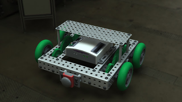
In this tutorial we will be making a Squarebot. You will need following materials to build your robot.
You can either part by part of you can directly buy the VEX Starter KIT. This is pretty expensive so if you consider buying in separate parts on eBay, it might save you few bucks. But keep in mind that Building VEX is expensive, its a professional system and it can perform impressive advance tasks, if you are a Robotics enthusiast you will find it pretty intimidating. Just take a look at this video showing capabilities of VEX Robotics.
Building Instructions
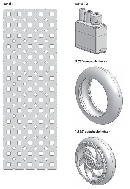
Lets start building your robot, first identify your materials and make sure you wont mount the wrong piece in wrong place. Please follow the guide bellow to identify materials.
Image Courtesy : ROBOTC
Step 1. Making Inner chassis rails
You will require two chassis rails one facing towards the other. Both should be kept in left and right positions with open side facing each other. Please orient them like below.
Mount the bearing flats to the chassis using two ½" 8-32 screws and two keps nuts. As shows.
Step 2. Making Outer Chassis rails
Just like the previous step you will require two chassis rails and position them according to the previous step
flat should be aligned with the eighth hole from the front end of the chassis rail, in the
middle row of holes.
Your outer rails should look like this
Step 3.Motor Assembly
Before starting on your motor make sure that you have installed the clutch
Insert two square beams to each clutch, to make sure they attach firmly. Square bar will act as motor's rotor.
Take the inner chassis rails which you have assembled before and put your motor square beams through the middle hole in the middle row of each chassis rail.
Install one bearing flat on the outward-facing side of each chassis rail, with the front hole of the bearing flat sliding onto the motor shaft as shown.
Your assemble so far should look like this.
Secure the bearing flat to the inner chassis rail and motor using two ½" 6-32 screws per motor. Note that these are the thinner screws, not the usual 8-32 ones

We're done with motor assembly and your project should look like this.

Step 4. Chassis Sub-assembly.
Insert a 3" square bar through the center hole of each unoccupied bearing flat, as shown.Do not push them all the way through. Push the end of the bar about ¼" through the rail.
Slide metal collars (with threaded screws) onto each of the 2" and 3" square bars,mounting them flush with the surface of the bearing flat against which they will sit.Be sure the square bars don’t get pushed further in while you put the collars on.

Once the collars and bars are in position, tighten the threaded screws with the thinner allen wrench to keep the collars from sliding out of place.
Slide a 60-tooth gear onto the drive axle of each motor, pushing it flush against the collar that you added in the previous step.
Slide a 36-tooth gear onto each of the remaining square bars, pushing them against the collars.
Add another collar to the end of the 2” shafts (the ones directly connected to the motor).Slide them down so that they are flush with the larger gear. Make sure they are tightened.
Tighten the threaded screws with the thinner allen wrench.
Your kit includes two differently sized black spacers. Slide one of each onto the shafts with the smaller gears (those not directly connected to the motors), as shown.
Install the pre-assembled outer chassis rails onto the current assembly. All three of the square bars sticking out of the inner rail should go through bearing flats on the outer rail.
Place chassis bumpers on the front and rear of the chassis rails, as shown.
Secure the vertical faces of the chassis bumpers to the end of the chassis rails using four ¼" 8-32 screws and keps nuts in the front, and four in the back.
Connect four 2” standoffs using four ¼” 8-32 screws. Place them as shown and be sure to note that two of them are on the edge and two are one space away from the edge.Connect the parts using the thicker allen wrench while holding the standoff in place.
Secure the horizontal faces of the chassis bumpers to the top of the chassis rails using four ¼" 8-32 screws and four keps nuts, two in the front and two in the back.
Install the small green tires (2.75" Removable Tire and 1.895" Hub) on the 3" square
beams, as shown. Slide them down so they are flush with the bearing flats.
Slide the collars onto the shafts such that they are flush against the wheels.Tighten the collars in place with the thinner allen wrench.
Position the micro controller on your robot as shown.
Attach the micro controller to the chassis using four ½” 8-32 screws and keps nuts,as shown. Insert the screws into the small holes in the micro controller to hold it in position properly.
Step 5. Canopy Assembly
You will need a punched panel to begin constructing the canopy.You are constructing a separate part in this segment, which will later be attached to Squarebot.
Attach the receiver to the punched panel using four ¼” 8-32 screws and four keps nuts as shown. Be sure to leave one empty row of holes on the left of the receiver.
Attach the antenna holder using a 3/4” 8-32 screw and keps nut, securing the screw through the middle hole on the left edge of the canopy. Then, slide the yellow antenna wire from the receiver inside the antenna sleeve and place it into the antenna holder.
If you are using a VEX rechargable battery pack, attach the battery strap along the back
row of the punched pannel using two ½” 8-32 screws. Be sure it is oriented properly
Take the blue rechargable Vex battery and orient it as shown. If you are using the blue
VEX AA battery holder, simply attach it to the canopy in place of the battery pack.
Lock the battery into place using the battery strip.
Attach the canopy to the robot. To do this, secure the canopy onto the four offsets you attached earlier using four ¼” 8-32 screws.You will have to offset the canopy by one hole either to the left or the right.
Step 6. Wire Assembly
Plug the wire that is attached to the left motor into “MOTORS” port 3 on the
micro controller.
Plug the battery into the back of the micro controller
Take the 9” RJ-10 wire (the yellow wire that looks like a phone cable) and plug one end
into the back of the receiver module. Plug the other end into the port marked “Rx 1” on
the back of the micro controller.
Final Look of our Square Robot.
Notice that this robot's Canopy is mounted above the micro controller
So that's all for the part one, You've just learnt how to make your own robot. From this part we will be only covering the Hardware part of your robot. To learn about how to write a software for your robot please go to PART 2


0 comments